
Author: Aldux
Trajectory Controller
A while ago, we reviewed how a hover controller works, in this post we are going to discuss how to go a bit further and create a trajectory controller.
In that previous blog post we discussed about how to control a drone to make it hold a specified position. This refers to the part of Control in the GNC argo. This refers to the manipulation of the forces, by way of steering controls, thrusters, etc., needed to track guidance commands while maintaining vehicle stability.
In this part we are focused on the Guidance. This refers to the determination of the desired path of travel (the “trajectory”) from the vehicle’s current location to a designated the target, as well as desired changes in velocity, rotation and acceleration for following that path.
There is several steps before we can achieve this. Mainly the next ones:
- Fly the vehicle using the flight stack
- Design a controller that will track/hold a specified position
- Create a trajectory, based on time and other factors
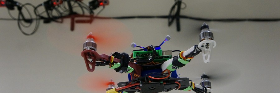
For the first part, in this blog we will use Altax Flight Stack, that compromises a companion computer and a flight controller. In this particular case I’m using a naze32 as flight controller, and two companion computers: Raspberry Pi 2 and oDroid U3.


The naze32 is connected to the Odroid U3 via a usb cable (a very short one). The vehicle is a 330mm rotor to rotor fiber glass frame, with 7×3.8in propellers, 1130kv motors, 15amps ESCs and a 3000mah 10C battery. It will fly for 11-13 minutes.
The Odroid U3 is running Ubuntu 14.04.1 in a eMMC module, which makes it boot and run generally faster. Its being powered by a BEC that is connected to the main battery.
The companion computer will “talk” a special language in order to send commands to the vehicle, this one is described here. And the most important part is that it will run the DronePilot framework. This framework is the that will pilot the vehicle.
For the second part (position controller), you can refer to this page to see how it works.
And now the trajectory part…
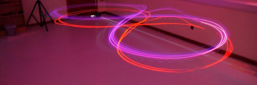
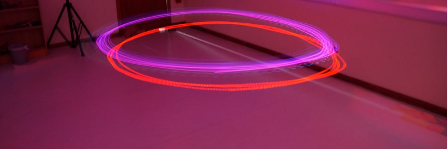
We need to generate certain X and Y coordinates that then it will be “fed” to the position controller at a specific time. We are going to create two types of trajectories, circle and a infinity symbol. Why this ones? because this ones are easy to generate and perfect to excite all the multi-rotor modes.
How to generate a circle trajectory??
This one is very simple… there is basically two parameters needed… Radius and angle. In our case the angle part we are going to combine it with the step time of the main loop of the controller and pi… basically the angle one will go from 0 to 360 degrees (in radians of course). The code looks like this:
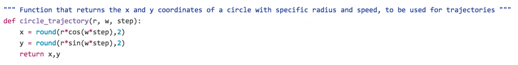
So, if we declare “w” like this: (2*pi)/12 it means that the trajectory will take 12 seconds to complete a full revolution, and then start over. This is the parameter that we will change if we want the vehicle to travel faster. Its better to start with a slow value, and then progress to faster trajectories.
The next step is to “fed” this coordinates to the position controller inside the control loop. That is done in this script.
The infinity trajectory is a special one! this one is called in several ways: Inifity trajectory, figure of eight… And there is several ways of how to calculate the coordinates, you can see in the next gif the posibilites of how to create a figure of eight:
The one I like the red dot one! why is this?? that one is called the Lemniscate of Bernoulli, which is constructed as a plane curve defined from two given points F1 and F2, known as foci, at distance 2a from each other as the locus of points P so that PF1·PF2 = a2.
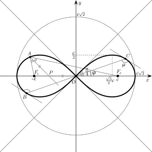
This lemniscate was first described in 1694 by Jakob Bernoulli as a modification of an ellipse, which is the locus of points for which the sum of the distances to each of two fixed focal points is a constant. We can calculate it as a parametric equation:
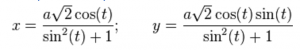
And then the rest is feeding that information to the position controller which will try to follow that trajectory as the dots on the plots. Magic.
The cool video can be seeing here:
pyIRCamera
In this post, I’m going to describe how to read a I2C sensor using a Raspberry Pi. The sensor I’m interested on reading/using is actually a InfraRed camera.
This camera comes (originally) from a Wiimote controller.
I spend this weekend developing a tiny python module that will interface to this wee camera.
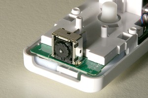
What is a PixArt?
This device is a 128×96 monochrome camera with built-in image processing. The camera looks through an infrared pass filter in the remote’s plastic casing. The camera’s built-in image processing is capable of tracking up to 4 moving objects, and these data are the only data available to the host. Raw pixel data is not available to the host, so the camera cannot be used to take a conventional picture. The built-in processor uses 8x subpixel analysis to provide 1024×768 resolution for the tracked points.


The is lots of extra technical information about the Wiimote: http://wiibrew.org/wiki/Wiimote#IR_Camera
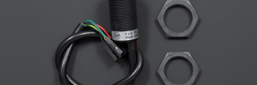
The sensor used for this library is a very good package made by DFRobot, important links:
- To buy it: http://www.dfrobot.com/index.php?route=product/product&product_id=1088#.VvlgYBIrKso
- Wiki: http://www.dfrobot.com/wiki/index.php/Positioning_ir_camera
The how-to for using the sensor, and the python module is on my github page, click here to go.
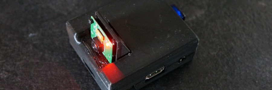
In the next image you can see the sensor picking the IR light coming from a Zippo:
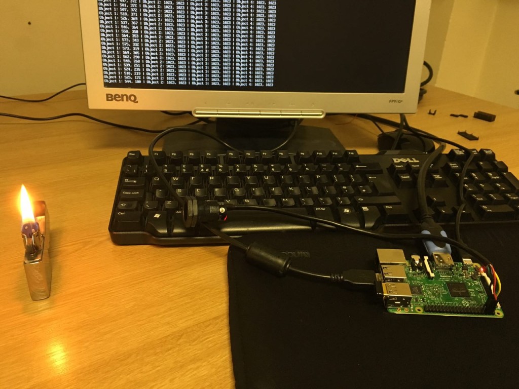
The python module will report the X and Y from the center of the IR source, it actually read up to 4 IR sources at the same time.
If you are looking to build a “light tracker” robot, or perhaps a precision landing for a multirotor, this sensor is worth to consider! Why?? just because the computer vision is already done inside the camera and it can work up to 100hz tracking IR objects… so, is a super super fast sensor!
A video of this sensor in action can be seen here:
Low Latency Raspberry Pi video transmission
In this post I’m going to explain how to make a very low latency video transmission using a RPI and a RPI camera. I have done a demonstration of this technique and posted a while ago a video, but I never publish how to actually do it, you can see the video here:
What will you need?
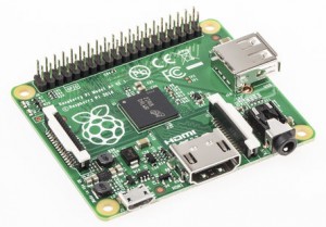
- Raspberry Pi: No matter which one, I’m using a RPI A+ (because of its small size, it can be used on small drones, like racers 😉 ), the RPI must be running raspbian, just that.
- Raspberry Pi camera module: There is nothing as fast as the CSI port…
- Wifi dongle: To connect the rpi to your network. You can actually make the rpi create a ad-hoc network or in any case your ground computer can do it.
- Ground computer: In this case I’m using a Mac to receive the data, the commands might be transferable to windows, but I don’t own one (Thank to all the gods out there :P), so, this will be “terminal” oriented.
How to?
- The rpi and your computer must be in the same network, and you must know the IP addresses of both devices.
- The mac must do a ssh connection to the rpi in order to activate the command.
- On a terminal window of the mac, execute this line:
netcat -l -p 5000 | mplayer -fps 60 -cache 1024 -
- Create a fifo file on the rpi (must be done only once…), by doing:
mkfifo video - On the ssh terminal window of the rpi, (replace the IP address to the one of your pi) execute this command:
cat video | nc.traditional 192.168.1.3 5000 & raspivid -o video -t 0 -w 640 -h 480
Then wait for 20 seconds and you will start seeing video:
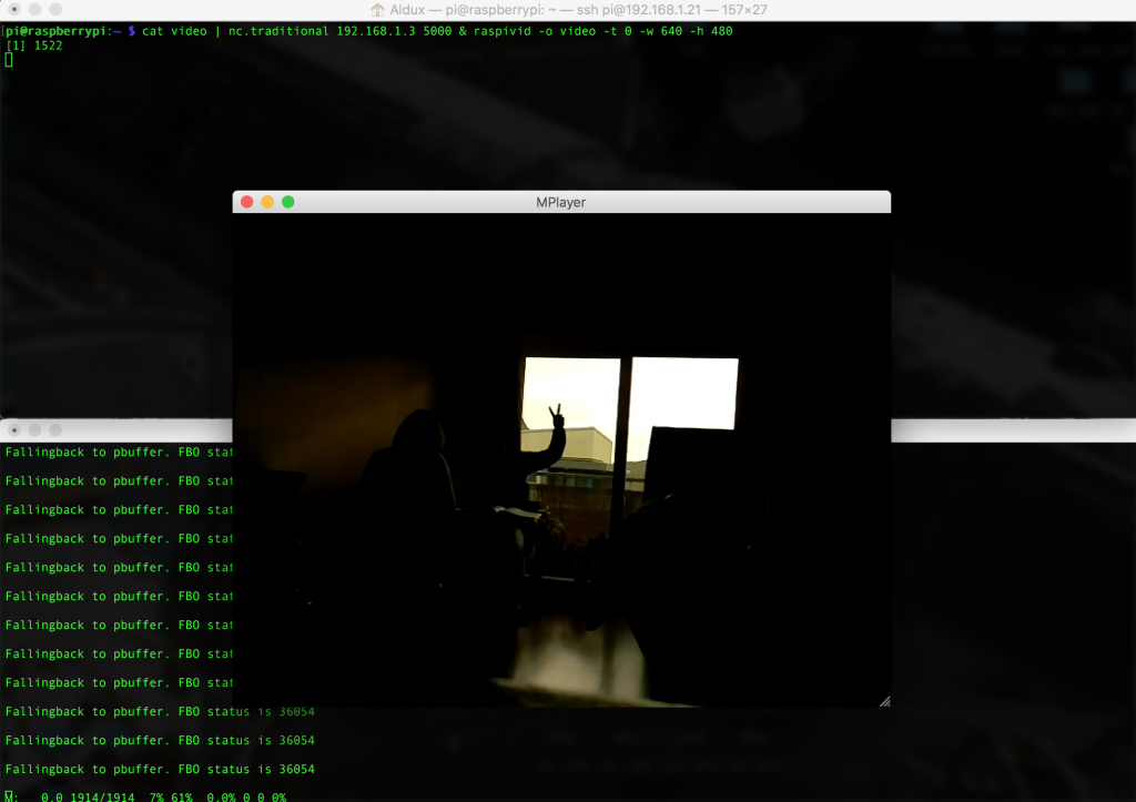
You might notice that at the beginning the video is not “synced”, but if you wait more seconds, the video will catch up and stay in that way!! and you can actually check the low low latency.
Tuneable?
Of course!!! you can change the width and height of the source on the rpi, of course, if you want the super extra low latency, then go for a lower resolution, also you can change the bitrate, but… you need to experiment to get the proper value.
Important to notice is that I have not try it flying yet… but if someone manage to do it and report back to me, I could make improvements to the code to make it easier to use.
In here you can see a video screen-shot of the entire methodology:
Another method?
Of course… There is tons of other several methods to achieve this… The extra one I’m going to show is the one using gstreamer.
GStreamer is a pipeline-based multimedia framework that links together a wide variety of media processing systems to complete complex workflows.
For making it work, you need to first install it, and on the raspberry pi, is done in this way:
sudo apt-get install gstreamer1.0
Also, in the computer receiving the stream, it needs to be installed, I’m using Mac, so, you need to install it using brew, and is something like this:
brew install gstreamer gst-libav gst-plugins-ugly gst-plugins-base gst-plugins-bad gst-plugins-good
brew install homebrew/versions/gst-ffmpeg010
When this is done, then we can actually activate the streams… this is done by executing this line on the RPI:
raspivid -n -w 640 -h 480 -t 0 -o - | gst-launch-1.0 -v fdsrc ! h264parse ! rtph264pay config-interval=10 pt=96 ! udpsink host=192.168.1.3 port=9000
This will activate a stream server and send it via UDP to a host (you need to change the IP address and port to the ones you use). Also you can change the settings on raspivid, like width, height, bitrate and lots of other stuff. I’m using VGA resolution, just to make it super fast.
Now, to receive and display the stream on the host you need to execute this command:
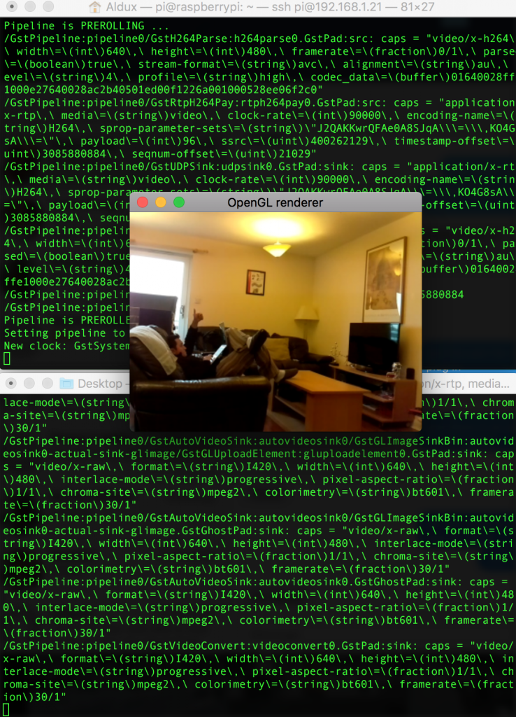
gst-launch-1.0 -v udpsrc port=9000 caps='application/x-rtp, media=(string)video, clock-rate=(int)90000, encoding-name=(string)H264' ! rtph264depay ! video/x-h264,width=640,height=480,framerate=30/1 ! h264parse ! avdec_h264 ! videoconvert ! autovideosink sync=false
This will one a wee window and start displaying video… something like this:
The good thing about this method, is that we can actually get that stream into apps such like Tower from 3DRobotics, and fly a drone using the telemetry and the video at the same time, something similar to DJI Lightbridge, but without paying the thousands dollars this system costs.
On the RPI, you need to execute this line:
raspivid -n -w 640 -h 480 -t 0 -o - | gst-launch-1.0 -v fdsrc ! h264parse ! rtph264pay config-interval=10 pt=96 ! udpsink host=192.168.1.9 port=9000
And on the tablet side… you need Tower Beta, and then just configure the stream port to fit your own…


Hover Controller
We all love drones, and we love to just buy one and go outside and make it fly by itself, this is great. But what is actually going on inside the drone? In this post I’m going to explain a bit how a loiter controller works, with the difference is that I’ll show my controller, share the python code and that I’m using a motion capture system inside my lab. The great MAST Lab.
First things first, you can check the code here. And secondly, I need to explain our setup.
We are using Altax Flight Stack which is a tuple of computers connected with each other and sharing information. The flight controller is a very cheap naze32, running baseflight (but cleanflight will work as well), and the companion computer is a Raspberry Pi (any version will do the work…). The entire script does not consume too much CPU.
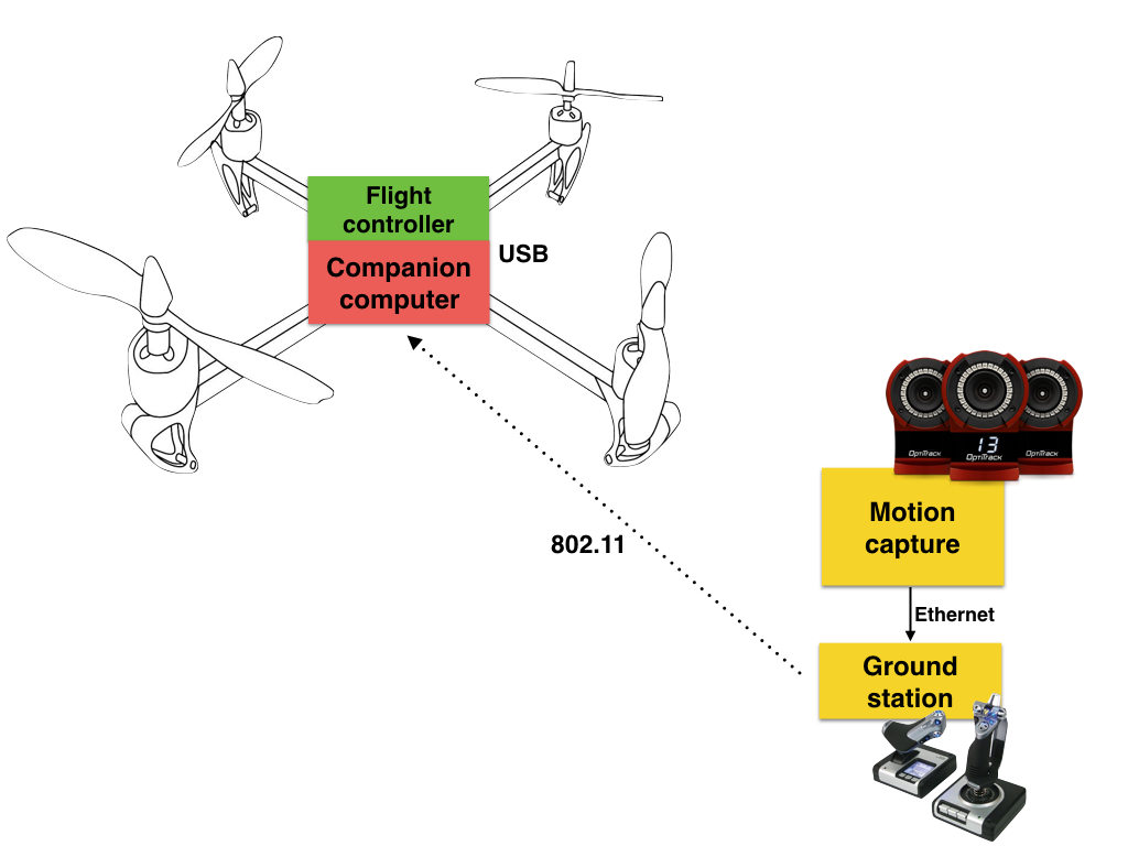
The connection diagram is showed above, the motion capture system is connected to a desktop computer and this computer sends the mocap data and the joystick information via a common wireless network (UDP), this information is used by the raspberry pi to know the position and attitude of the vehicle, then the rpi calculates a set of commands (roll angle, pitch angle, yaw rate and throttle) using simplistic PID controllers and then it sends the information to the flight controller.
This outer loop control is working at 100hz, but it can be configured to go slower.
Important to notice that we have crashed lots of times when starting to test/debug this system. Most of the crashes are due to the desktop computer “hanging out”… then the vehicle stops receiving the information and will keep the last command. A auto-landing feature is needed, this feature will be added on version 2.
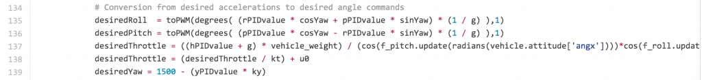
In the part of the control, we are using angle mode on the inner loop (naze32) and then we calculate the appropriate angle commands (pitch and roll) from desired accelerations (outputs of the controllers) to make the vehicle hold the commanded position in the space.
The most important part of the code is when we calculate desired angle commands from the desired accelerations coming from the PID controllers:
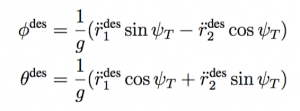
And the proper math:
The rest of the code is just to deal with data, vehicle and make everything work on threads. One thread for the control and another for receiving the data.
The code is extremely easy to understand and to tweak (I hope…). With this setup, the joystick is the one that activates the automatic behavior, if the proper switch is on manual, then you will be able to fly the vehicle using the joystick.
This is by no means the same technique used by Pixhawk in loiter mode. But perhaps is a nice way to start learning about flight modes (and controlling aerial vehicles) so that then you can learn how advanced flight modes developed by the team of PX4 and 3DR work.
The video is here:
More pictures:


Many thanks to my good friend Murray to help me develop the controller, also to my {friend/lab assistant} Kyle and my great {students/camera operators} Hunter and Kenny.
CV on video stream
This short demonstration/video is about how to use one of my simple, yet powerful, computer vision scripts to detect a color, but in this case, the video is going to be coming from a wireless camera.
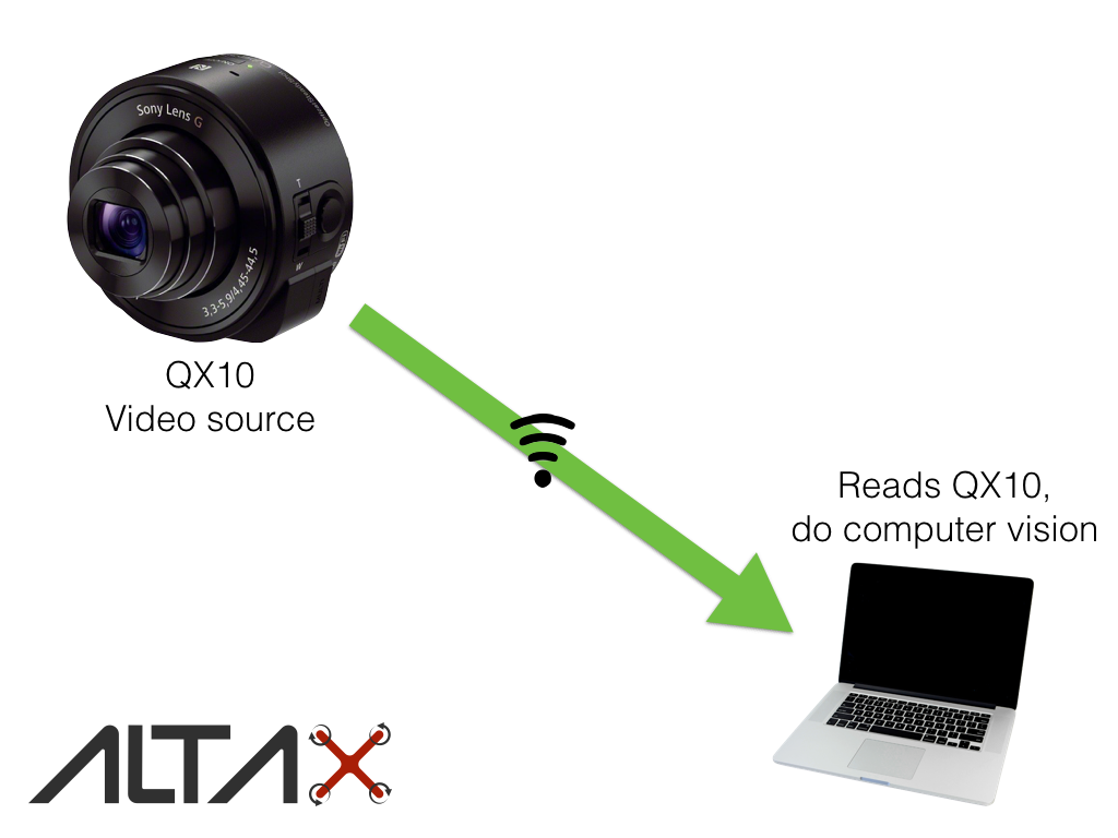
On the above diagram, you can see how is everything connected.
The QX10 has the capability to send stream of JPEGs to a device connected to the wireless network this camera creates when its turned on.
To access this stream you need to read and use the API supplied by Sony and its now always very clear… But I managed (after a few attempts) to read the stream using python and openCV, and then a quick modification to one of my scripts, you can find the code here.
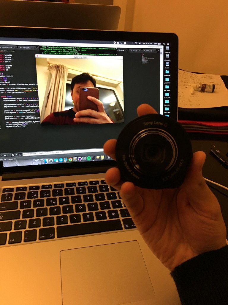
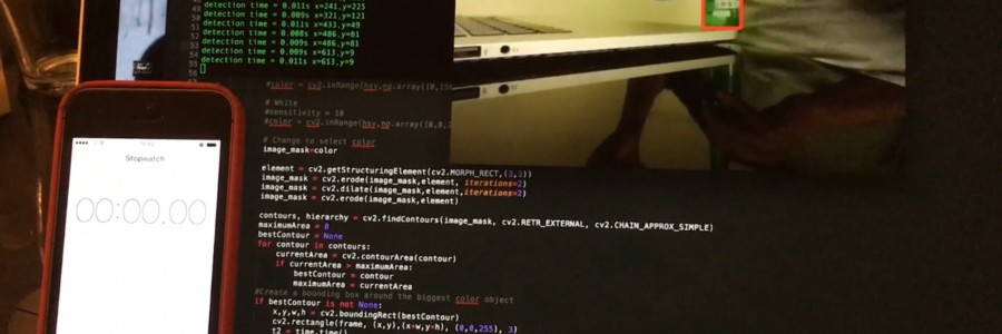
I did a small video doing a demo of this script. In this script the target is to find the color green and put a box around it.
The most important part (for me, anyhow) is to check the times of the transmission and the detection of the color. This is the latency… If you pause the video when I’m displaying the iPhone in both screens (one the real and the other one the transmitted image), then we can see that the latency of the stream is around 0.3-0.5 seconds, in average 0.4 seconds. Is not that bad actually.
Check the video, and leave your comments.
How to DroneKit SITL
Software in the loop, is a software testing technique that will help you test your software using simulations before doing it with real/physical systems. ASAM defines a generic simulator interface as:
Definition of an API between test automation systems and test-benches such as HIL-systems (hardware-in-the-loop) or SIL-systems (software-in-the-loop). Provides access to the simulation model, ECU internal measurement and calibration data, diagnostics data, the electrical error simulation unit and the ECU network. API is described as a technology-independent UML model.
In the case of our beloved drones, we will use SIL techniques to crash them virtually before attempting to test our software on real expensive hardware.
Thanks to the developer team from 3DR, they have developed a full simulator that allows you to run APM Plane, Copter or Rover without any hardware. It is a build of the autopilot code using an ordinary C++ compiler, giving you a native executable that allows you to test the behaviour of the code without hardware.
The main issue is that sometimes it gets tricky to make it work… or to make it properly…
This small guide will help people who is having problems make it work (also for me when installing it on new systems :P)
Assumptions:
- This guide is for Mac users (maybe I’ll make a post for windows…)
- If you have a android tablet, it will work as well (as complement)
- You know basic stuff on Mac (like using terminal, brew, pip)
- Brew, pip and python installed
Having said that, lets start the process…
Installation.
We need basically 3 things, dronekit, dronekit-sitl and mavproxy. MAVProxy is a command-line UAV ground station software package for MAVLink based systems. MAVLink is the “language” that our beloved drones talk.
Steps:
- Update brew:
brew update
- Update your pip:
pip install --upgrade pip
- Install Dronekit:
pip install dronekit
- Install SITL:
pip install dronekit-sitl
- Install MAVProxy (execute line by line:
brew tap homebrew/science
brew install wxmac wxpython opencv
pip uninstall python-dateutil
pip install numpy pyparsing
pip install MAVProxy
Usage.
The most simplistic usage for this set of tools, is to send commands to a simulated vehicle to take off and land… and see on the screen how is doing it.
To achieve this, we need to create a virtual vehicle and then connect MAVProxy to it, and make MAVProxy spread the information to several devices/applications.
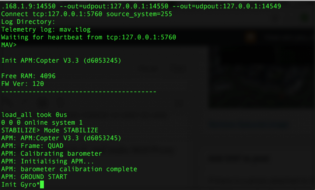
Create a vehicle (on one terminal):
dronekit-sitl copter --home=55.870595,-4.287639,0,0
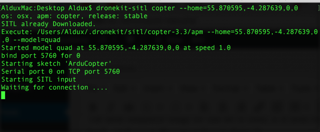
Allow me to explain what I’m doing on this command:
- copter -> SITL can do plane, copter, rover… I’m making this virtual vehicle a multicopter.
- –home=55.870595,-4.287639,0,0 -> Making the home of the vehicle outside of the building I work.
Start MAVProxy (on a different terminal):
mavproxy.py --master=tcp:127.0.0.1:5760 --out=udpout:192.168.1.9:14550 --out=udpout:127.0.0.1:14550 --out=udpout:127.0.0.1:14549
Allow me to explain what I’m doing on this long command:
- –master=tcp:127.0.0.1:5760 -> I here we declare how to connect this mavproxy instance with the virtual vehicle (drone-kit-sitl creates a TCP connection with a specific port and waits until something connects… In our case, MAVproxy will connect to it.
- –out=udpout:192.168.1.9:14550 -> I’m making mavproxy proxy all of the information is receiving from the virtual vehicle to a particular IP using UDP… this IP happens to be the one of my tablet. So, as long as my tablet is connected to ALTAX-network, it will be receiving the information of the virtual vehicle.
- –out=udpout:127.0.0.1:14550 -> Same as above but using localhost, so… mavproxy will proxy the information to my mac using UDP… sounds kinda weird, but this is for using another application like “APM Planner” or “qgroundcontrol” and see the same information as the tablet will see.
Open applications:
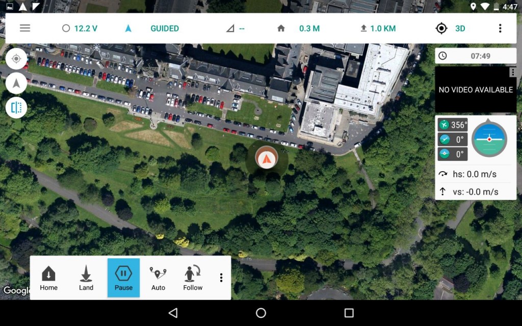
Now, whats rest to do is open a application that will show us “graphically” how the vehicle is doing… just as if it was REAL!! so, go and open “qgroundcontrol” on the mac…
And on the tablet, open “Tower”, and change the telemetry connection type from “usb” to “udp”… thats it!
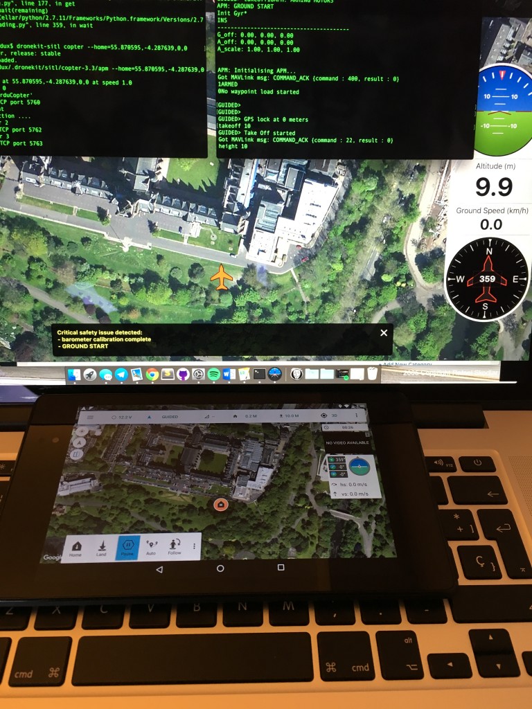
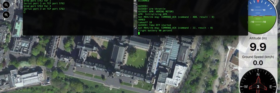
Take off!
Ok, let make the vehicle move or do something fun… execute this lines (as they are written, literally) on the terminal window that is running MAVProxy:
- mode guided
- arm throttle
- takeoff 1000
With this commands you will make the vehicle start flying till it reaches 1000 meters (mental!!!) and then wait, or “loiter”, of course, the battery will start to run out, but no worries, is virtual!
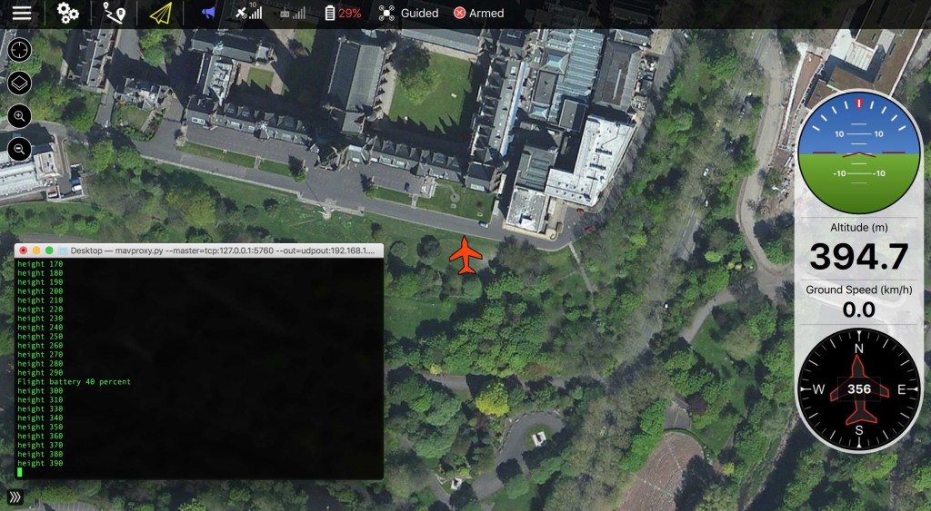
If you want your vehicle to land, then just type: “mode land”
Congratulations, you just made a virtual vehicle take off, fly to 1000 meters and then hit ground at 0.509052 m/s. Go have a beer, you earn it.
Altax Flight Stack
Flight Stack
I’m currently using two (or more…) computers onboard my drones, one computer is in charge of stabilisation and control of the vehicle (g.n.C) while the other handles the guidance and navigation part (G.N.c), in this post I’ll define and will give a short explanation of my flight stack.
G.N.C. is is a branch of engineering dealing with the design of systems to control the movement of vehicles, especially, automobiles, ships, aircraft, and spacecraft. At this moment my main focus is aircraft, and in more particular sense, multirotors. In many cases these functions can be performed by trained humans, pilots… however, because of the speed and complexity of flight dynamics of multirotors, human reaction time is too slow to control this movement, or even impossible to control 4 actuators in order to make a quadcopter fly. Therefore, systems are used for such control. Even in cases where humans can perform these functions, it is often the case that GNC systems provide benefits such as alleviating operator work load, smoothing turbulence, energy savings, etc. In addition, sophisticated applications of GNC enable automatic or remote control.

Flight Controllers
To handle the stabilisation and control of the vehicle I use off-the-shelf flight controllers, and I use several of them Multiwii (several models), APM, PX4, Pixhawk, CC3D among others. The ones I tend to use harder are the Multiwii boards and the Pixhawk.
MultiWii

You might be asking yourself which multiwii board I use?? and the answer is simple, whichever. I wrote a python module that talks the multiwii serial protocol (pyMultiwii) and thats how I communicate with that flight controller. So, any flight controller board that uses the multiwii firmware or that it equipped with MSP (multiwii serial protocol) is going to work with my module. I have tested my module on the next multiwii boards:
- MultiWii AOI v1 and v2
- MultiWii lite v1
- MultiWii SE v2
- NanoWii
- MultiWii 328p
- Afro Naze32
- Naze32 (complete)
The new trend among flight controllers is to use 32bit microprocessors (usually at 72mhz…), and the new MultiWii’s are 32bit versions with similar sensors as the old ones, of course the firmware is different, and the vehicle attitude control is much more smoother in comparison with the 8bit boards, due to faster processing and the use of better precision (float or double) on the calculations. A very noticeable performance occurred after using the new board version, the position controllers performed 70% better after having a faster inner loop (attitude stabilisation).
And between those new flight controllers, there is two “similar” firmwares, baseflight and cleanflight. I will not go into detail about this situation. Currently I’m using baseflight, although I have reports from other people that my module also works with cleanflight.
Pixhawk

The pixhawk is a flight controller designed by ETH Zurich which started with the development of the PX4 autopilot and then to its new form know as pixhawk, it supports several flight stacks, the most popular/most used is the 3DRobotics (APM Flight Stack), which is right now the second largest consumer drone company in the world. The other flight stack is the “PX4 Flight Stack”.
On the hardware side, it uses a 32 bit processor clocking at 168mhz and two IMU’s instead of just one to provide redundancy to the system. I will not go to much into detail about this.
Being an open source open hardware project, several “versions” of the pixhawk have already appeared on the market, also several chinese clones… I have tested several versions of the pixhawk, among this ones:
- PX4 (original)
- 3DR Pixhawk
- Pixhawk (HobbyKing clone)
- Pixhawk Lite
Although the chinese clones are far more cheap to get than an original version, I personally recommend to use the original ones, this ones have being more tested and go through more strict quality control methods and therefore must likely less to fail. And when you’re flying over the Atlantic… you want something that will NOT fail.
There are several alternatives to talk to this flight controller. And either the PX4 and APM flight stack, both talk “mavlink” which is a protocol for communicating with small unmanned vehicle. It is designed as a header-only message marshaling library. Its being adopted by several other flight controllers, its was done by Lorenz Meier… and you guess correctly, from ETH Zurich.
As I was saying, there is two ways of talking to the FC, one is using the 3DR option called “DroneKit”, I have use it to make several examples, it has its limitations and its practicalities.
The other one is to use ROS.
If I have enough time I’ll make a post describing both options.
Companion Computers
So, after introducing the flight controllers (the ones that are in charge of the “inner loop” or the stability of the aircraft), I’ll proceed to discuss a bit about the companion computers.
This depends entirely of the target mission you want to accomplish, in my case, I’m developing position controllers for multirotors… I have to mention that we can actually just use the FC to develop position controllers… but is a bit more complicated to modify tons of code on the firmware of either naze’s of the PX4/APM flight stack rather than separating the “outer loop” to be executed on another computer. That’s where the companion computers come into action. Also is better if you separate computers so that you can have a bit more of robustness, if the companion computer crash, the FC is still able to keep stabilising the vehicle and (with properly tuned failsafes) probably land the vehicle or disengage it.
There is a boom of linux credit-card size computers nowadays that we can make use as companion computers. Personally I like to use Raspberry Pi’s, due to its simplicity, robustness and low price. And now with the new Pi Zero, the things get very very small and light.
Companion computers I have used on my vehicles:
- Raspberry Pi B+
- Raspberry Pi 2
- Odroid U3
I have had accidents with the RPI’s and those small computers are really sturdy. The RPI 2 is great when you want to run some computer vision algorithms and then command the vehicle to do certain commands. But having a RPI B+ (if you have one laying around) it work great.
Right now I have two exact same vehicles with naze32’s and RPI B+ doing position controls, and they work quite alright.

Flight Stack
So, whats the big deal having another computer on board? well… you have more computer power, you can do more complex stuff or you can interconnect more devices to the vehicle or even turn the vehicle into a IoT device.
In my most simple case I used it to get readings from the ground station which can contain, motion capture data, joystick commands or even calculated control commands.

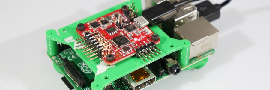
In the case of the naze32 I just simple connect a usb short cable to the rpi and to the board. In the case of the pixhawk there is two ways of connect it, one using the rpi onboard serial interface or to use a FTDI cable/board to make them talk together. I have tested almost all connections possible.
I designed and 3D printed a small base that is bolted to the rpi and holds either the naze32 or a pixhawk. It makes everything tidier and works alright. I’ll upload it to Thingiverse and share it as well.


Wind Tunnel
I had the opportunity to perform some flights inside the University of Glasgow Wind Tunnel Facilities, also called “The De Havilland Tunnel”, which has a test section of 9ft × 7ft (2.7m × 2.1m) and can do maximum speeds of 70m/s (156mph).

This video (if its good enough…) it will be use for promotional material around the University of Glasgow.
I chose my new hexacopter racer to do this work, and I just outfitted a video transmitter and a mobius camera. My idea was to perform the flights doing FPV, but due to the “tight” spaces between my vehicle, the tunnel and the model installed (metallic scale model of an airplane) it was too risky to do it in that way, so I had to get inside the tunnel and perform the flights using my eyes, this also proved to be complicated, but at the end I managed to get some footage that will be analysed by media team to see if the can insert it somewhere on the promotional videos…
Something to consider is that if you are in a tunnel, close to the ground, you will suffer from ground effect and will cause instabilities… while being to close to the ceiling, it happens something similar, the rotors have more trouble generating the lift to keep the vehicle level and in the same altitude, and also causes some nasty behaviors on the vehicle.

The only thing that did not happen was crashes… I tried to be extra careful to avoid hitting the tunnel and more particular, the model.
I produce some great gifs:
And a great video: