Drone following a roomba

Drone following a roomba

Oh!! it’s been a while since I write a blog!

I’m sorry for that! Very busy at the moment!

In this post I will explain about a very cool robotics project I did last year. This project is as cool as it sounds: making a drone follow a roomba using computer vision!

The idea can be broken down in different sections, one the vehicle, the communications, the control, computer vision and results…

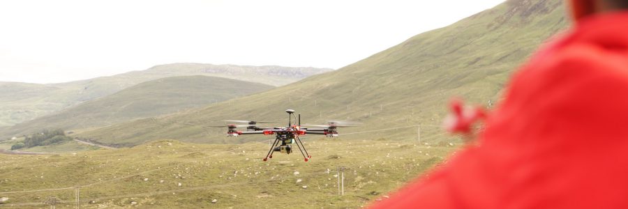
The objective of this project is to make a drone “see” a roomba and try to follow it from the air.

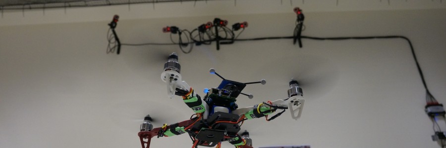
On the vehicle side, I was using the great and cool BigX, which is a great vehicle with very nice performance and big!! Here is a pic of it:

BigX

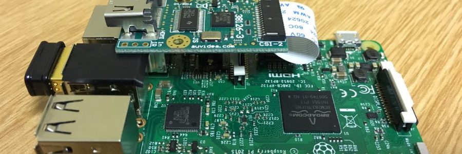
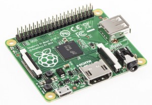
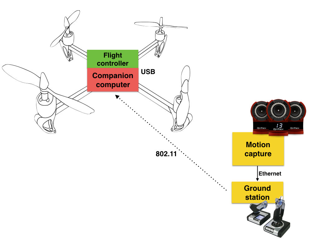
On board I was using the same concept of the Flight Stack, which is the combination of a flight controller (pixhack in this case) and a raspberry pi with extra features.

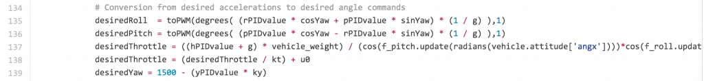
The RPI was a 3, and its the one in charge of “piloting” the aircraft when I’m not doing it. Also the RPI is the one that runs the computer vision algorithm to be able to “see” the roomba. With that information (position in pixels X and Y) the RPI will compute the necessary velocity commands to steer the vehicle to the center of the target.

The RPI was also in charge of the communications, it created a network and on the ground I was using a ubiquiti AP that was connected via ethernet to my MBPR, I used this configuration because such AP gave me the range of 10km LoS (I just try it up to 3km…)

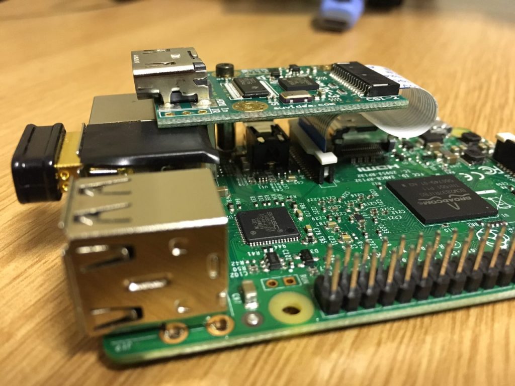
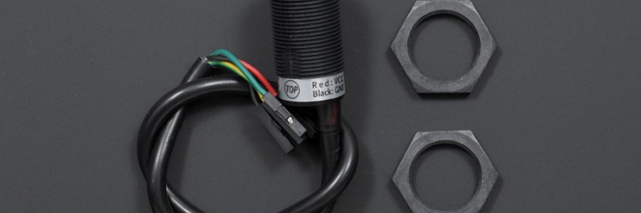
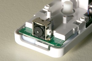
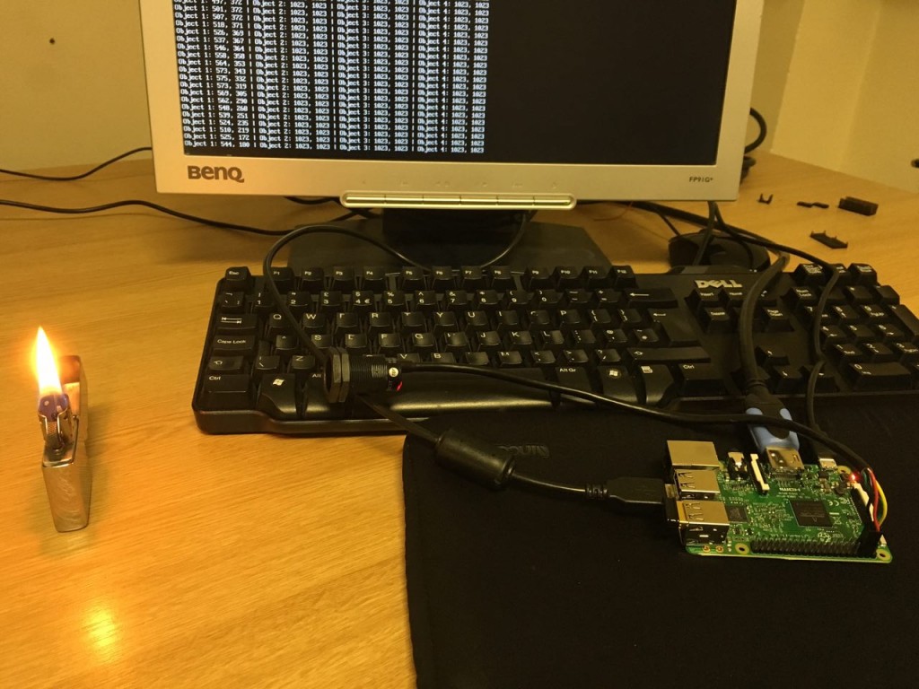
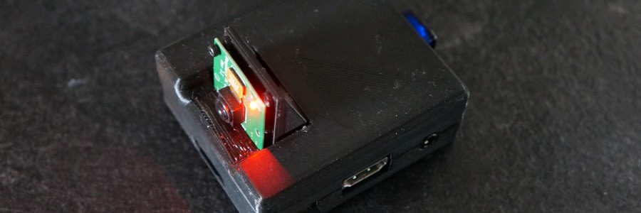
Also on board, connected to the RPI, a B101 HDMI bridge was used in order to capture the frames from the gopro camera and have them analyzed.

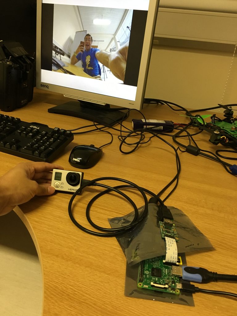
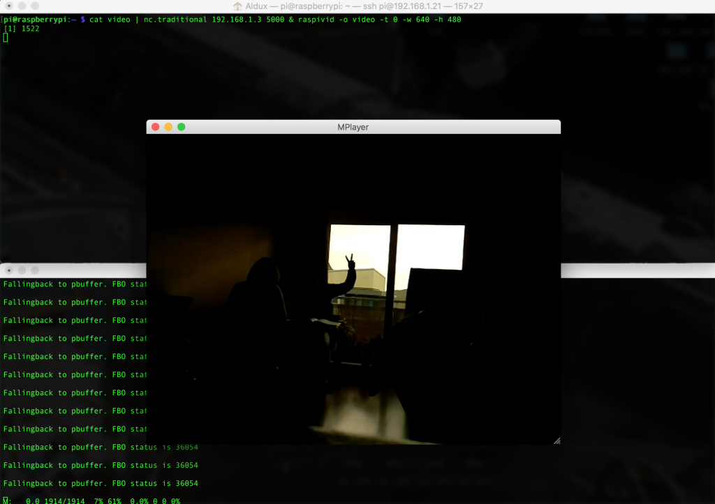
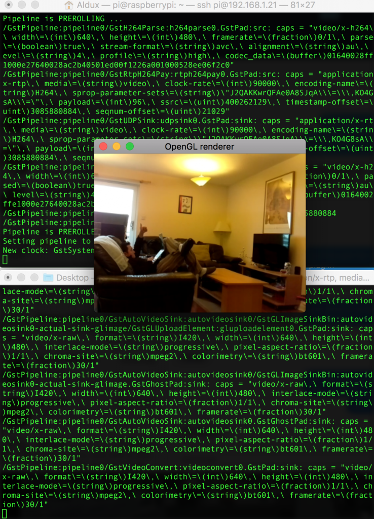
On the ground side as I mention before, I had the Ubiquiti AP and my laptop connected with ethernet to it. My computer logged in to the RPI via SSH in order to activate the scripts that run the main stuff. Also I had QgroundControl opened to be able to see the telemetry of the vehicle in a nice way. I was using mavproxy with udp casts. An image of how my computer screen looked was:

Ground Station Computer

In the image above you can see the position teleoperation tool from the AltaX ground station program. This module changed the position of the robot by reading the keyboard from the ground station computer, pretty neat…

On the computer vision part, I added blue tape to the top of the roomba in order to be very easy distinguishable from the environment. I also tuned as much as possible my different color tracker algorithms, you can find the code here and a video demonstrating here.

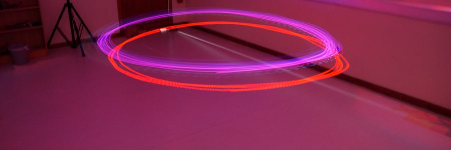
When you combine all ingredients, plus creating a velocity vector position control, you got a nice result, like the one showed in this video:


  • Camera: NEX-5R
  • Focal length: 16mm
  • ISO: 800
  • Shutter speed: 20s
Long autonomous mission

Long autonomous mission

Its been a while since I have some time to post in the blog. But with great powers come great responsibility hehe…

In this post I’m going to describe the process I did for the mission that was showed in the next video:

That was one of the longest autonomous missions I have done with a quadrotor. The vehicle travelled approximately 6.2km and the furthest it went from the operator was 3km. I decided to make this mission just to see if the vehicle was capable as well as the extra systems that accompany the vehicle.

The vehicle was also somewhat new, I build it and flew it 5-6 times before attempting this mission. The motors were great (4114 pro), I was using cf tarot foldable propellers and a modified cf frame.

Foldable quadrotor

These combination of components made a very efficient yet powerful vehicle, with an 5.2Ah battery, the vehicle was flying around 24min.

And as usual this vehicle contain the AltaX flight stack, which is just the combo of a companion computer and a flight controller. The companion computer is the Raspberry Pi 3, while in the flight controller I chose a pixhack. The pixhack is a version of the standard pixhawk but the IMU has internal dampening, which means not too much vibration isolation is needed, this was specially key in this frame as it does not have too much space…

Also in the communication side of things, I added a high-gain wifi dongle dual band. Such wifi dongle is powered using a BEC because by itself the rpi cannot supply enough power to have a decent range.

For camera, I was using a gopro hero 3, therefore the hdmi-csi bridge is needed. The gopro was mounted in a 3 axis gimbal, the tarot one… excellent gimbal for the gopro.

In the ground I had a directional AP that was always pointing towards the vehicle, that AP was connected to my computer using an ethernet cable therefore the network was complete. The AP I had was an Ubiquiti Loco M5, which had a great range!

So, the rpi was in charge of talking to the pixhack (via mavlink using dronekit), also running the AltaX Ground Station Console and finally transmitting the video back to the ground (video stream server).

For the video transmission, I used very similar techniques as in here. So, I was using gstreamer. The hdmi-csi bridge basically turns any hdmi device into a v4l2 device… so, it was very easy to pipe it using gstreamer.

My ground station console is basically like a pilot remote with extra power 馃槈 It is capable to send any kind of command to the pixhawk, like take off, change altitude, circle around, send a mission, manual reposition… you name it!

I chose the Scottish highlands as place to test this mission, because the remoteness of the place, I had no problems with regulations, since there is nothing around… even so, I followed the regulations in place in the UK.

The mission started by me taking off the vehicle, leaving it in loiter mode, then checking the console tool, upload the mission and start it with an enter. That sweet. Then after 17 stressful minutes, the vehicle was in sight… it was coming back, in either case, the telemetry was telling me where it was… let me say something, this loco m5 is quite a nice product!! I never reached half of the connection strength!

The main problem was at the end, the vehicle was flying head wind… therefore the motors required more juice in order for the pixhawk to maintain 5m/s… but at the end with the alarms making beep beep beep beep.. I was able to perform a somewhat hard landing. But everything was ok and the mission was successful!!

I would like to say sorry due to the low resolution of the screen recording… what happened is that I lost the original file and I only got this less-than-HD version… yuck.

In any case, I hope you enjoy the video, extra thumbs up to the person that recognizes the soundtrack!

Computer Vision Talk

Computer Vision Talk

What the funk?


In my most recent visit to Mexico, a very dear friend (Rolis) of mine (Aldux) invited me to give a talk about computer vision and the applications I usually use it for, which are drones of course!

Needless to say, I had a blast!! I talked a lot of the computer vision slung load technique that I used in my PhD thesis as well as the cool project I developed as Postdoc at the University of Oxford, the Kingbee project!

Also, a week before the talk, I created some new scripts on my popular computer vision repository, those ones relate to haar cascades.

Slung load recreation with microphone

One of the most interesting new items is a script that detects cars from a webcam… such webcam is an open traffic IP cam somewhere in the USA… One of the most complex parts when doing this script was to be able to open correctly the stream of images, then the haar cascade is very easily implemented, I took the trained xml files from other repositories similar to mine (proper source crediting is given of course).

You can see it in action here:

https://github.com/alduxvm/rpi-opencv/blob/master/car-detection-stream.py


Another cool script is one that detects people (the full body) again using as well haar cascades. This one comes from an IP camera in Spain, you can see it in action here:

https://github.com/alduxvm/rpi-opencv/blob/master/haar-detection-stream.py


The talk was given at聽my friends company,聽called Funktionell聽which is a pretty cool place! full of gadgets, electronics, 3d printers, engineers, programmers and designers!! Their statement is:

Somos una empresa de tecnolog铆a que se dedica a crear experiencias digitales inolvidables. Movidos por la innovaci贸n y la curiosidad por romper paradigmas, mezclamos la tecnolog铆a con la imaginaci贸n para llegar a resultados de calidad incre铆bles.

Finally, the video of the entire talk was posted on Funktionell facebook page, it can be seen here:

Visi贸n por computadora

Bienvenidos al #CodeMeetsFunk
Hablamos de Visi贸n por computadora aplicada en detecci贸n de rostros, colores y control de drones.
Ponentes: Gustavo Heras y el Dr. Aldo Vargas

Posted by Funktionell on Saturday, April 1, 2017


Aftermath
Slung Load Controller

Slung Load Controller

Multirotor Unmanned Aerial Vehicles (MRUAV) have become an increasingly interesting area of study in the past decade, becoming tools that allow for positive changes in today鈥檚 world. Not having an on-board pilot means that the MRUAV must contain advanced on- board autonomous capabilities and operate with varying degrees of autonomy. One of the most common applications for this type of aircraft is the transport of goods. Such applications require low-altitude flights with hovering and vertical take-off and landing (VTOL) capabilities.

Similar as before in this project we use the AltaX Flight Stack聽which is compromised by a Raspberry Pi 3 as companion computer and a naze32 as flight controller.

The slung load controller and the machine learning estimator is running on the RPI3, although of course the training of the recurrent neural network was done offline in a big desktop computer. The RPI calculates the next vehicle position based on the estimation of the position of the slung load, everything is running using our framework DronePilot聽and guess what? its open source ;). Keep reading for more details.

If the transported load is outside the MRUAV fuselage, it is usually carried beneath the vehicle attached with cables or ropes, this is commonly referred to as an under-slung load. Flying with a suspended load can be a very challenging and sometimes hazardous task because the suspended load significantly alters the flight characteristics of the MRUAV. This prominent pendulous oscillatory movement affects the response in the frequency range of the attitude control of the vehicle. Therefore, a fundamental understanding of the dynamics of slung loads as they relate to the vehicle handling is essential to develop safer automatic pilots to ensure the use of MRUAV in transporting load is feasible. The dynamics of the slung load coupled to a MRUAV are investigated applying Machine Learning techniques.

The learning algorithm selected in this work is the Artificial Neural Network (ANN), a ML algorithm that is inspired by the structure and functional aspects of biological neural networks. Recurrent Neural Network (RNN) is a class of ANN that represents a very powerful system identification generic tool, integrating both large dynamic memory and highly adaptable computational capabilities.

Recurrent neural network diagram

In this post聽the problem of a MRUAV flying with a slung load (SL) is addressed. Real flight data from the MRUAV/SL system is used as the experience that will allow a computer software to understand the dynamics of the slung in order to propose a swing-free controller that will dampen the oscillations of the slung load when the MRUAV is following a desired flight trajectory.

This is achieved through a two-step approach: First a slung load estimator capable of estimating the relative position of the suspension system. This system was designed using a machine learning recurrent neural network approach. The final step is the development of a feedback cascade control system that can be put on an existing unmanned autonomous multirotor and makes it capable of performing manoeuvres with a slung load without inducing residual oscillations.

Proposed control strategy

The machine learning estimator was designed using a recurrent neural network structure which was then trained in a supervised learning approach using real flight data of the MRUAV/SL system. This data was gathered using a motion capture facility and a software framework (DronePilot) which was created during the development of this work.

Estimator inputs-outputs

After the slung load estimator was trained, it was verified in subsequent flights to ensure its adequate performance. The machine learning slung load position estimator shows good performance and robustness when non-linearity is significant and varying tasks are given in the flight regime.

Estimator verification

Consequently, a control system was created and tested with the objective to remove the oscillations (swing-free) generated by the slung load during or at the end of transport. The control technique was verified and tested experimentally.

The overall control concept is a classical tri-cascaded scheme where the slung load controller generates a position reference based on the current vehicle position and the estimated slung load position. The outer loop controller generates references (attitude pseudo- commands) to the inner loop controller (the flight controller).

Control scheme

The performance of the control scheme was evaluated through flight testing and it was found that the control scheme is capable of yielding a significant reduction in slung load swing over the equivalent flight without the controller scheme.

The next figures show the performance when the vehicle is tracking a figure-of-eight trajectory without control and with control.

The control scheme is able to reduce the control effort of the position control due to efficient damping of the slung load. Hence, less energy is consumed and the available flight time increases.

Regarding power management, flying a MRUAV with a load will reduce the flight times because of two main factors. The first one relates to adding extra weight to the vehicle, consequently the rotors must generate more thrust to keep the desired height of the trajectory controller, hence reducing the flight time. The second factor relates to aggressive oscillations of the load for this reason. The position controller demands faster adjustment to the attitude controller which increases accordingly the trust generated by the rotors. The proposed swing-free controller increases the time of flight of the MRUAV when carrying a load by 38% in comparison with the same flight without swing-free control. This is done by reducing the aggressive oscillations created by the load.

The proposed approach is an important step towards developing the next generation of unmanned autonomous multirotor vehicles. The methods presented in this post聽enables a quadrotor to perform flight manoeuvres while performing swing-free trajectory tracking.

Don’t forget to watch the video, it is super fun:

UoG 360 Spherical

UoG 360 Spherical

Glasgow University area 360-degree spherical panoramic photo*.

DJI FC220
茠/2.2 4.7 mm
1/120 ISO 151


* Complying w/ UK Air Navigation Order (CAP393). Always remember to fly safe!


Computer vision using GoPro and Raspberry Pi

Computer vision using GoPro and Raspberry Pi

In this post I’m going to demonstrate how to do test some computer vision techniques using the video feed from a GoPro Hero 3 directly towards a Raspberry Pi 3.

I’m using a special bridge that has a HDMI input and as an output goes to the CSI camera port of the Raspberry Pi, so, basically as easy as using a RPI camera…

IMG_2634

This is actually not a very common technique to do, the bridge is from the company Auvidea, and the model is the B101.

And the best part is that its plug and play. I just install it on my RPI, connected the CSI cable to the camera port, turn my RPI on, turn the GoPro on, and run “raspivid -t 0” and voil脿, you will see the video on the screen!!!

Different angle of the rpi + HDMI bridge

After that is just question of using my computer vision repository:聽https://github.com/alduxvm/rpi-opencv, and start testing the different scripts… As usual, I created a video for you guys to see it working, take a look here:

Trajectory Controller

Trajectory Controller

A while ago, we reviewed how a hover controller works, in this post we are going to discuss how to go a bit further and create a trajectory controller.

In that previous blog post we discussed about how to control a drone to make it hold a specified position. This refers to the part of Control in the GNC argo. This聽refers to the manipulation of the forces, by way of steering controls, thrusters, etc., needed to track guidance commands while maintaining vehicle stability.

In this part we are focused on the Guidance. This refers to the determination of the desired path of travel (the “trajectory”) from the vehicle’s current location to a designated the target, as well as desired changes in velocity, rotation and acceleration for following that path.

There is several steps before we can achieve this. Mainly the next ones:

  1. Fly the vehicle using the flight stack
  2. Design a controller that will track/hold a specified position
  3. Create a trajectory, based on time and other factors

For the first part, in this blog we will use Altax Flight Stack, that compromises a companion computer and a flight controller. In this particular case I’m using a naze32 as flight controller, and two companion computers: Raspberry Pi 2 and oDroid U3.

The naze32 is connected to the Odroid U3 via a usb cable (a very short one). The vehicle is a 330mm rotor to rotor fiber glass frame, with 7×3.8in propellers, 1130kv motors, 15amps ESCs and a 3000mah 10C battery. It will fly for 11-13 minutes.

The Odroid U3 is running Ubuntu 14.04.1 in a eMMC module, which makes it boot and run generally faster. Its being powered by a BEC that is connected to the main battery.

The companion computer will “talk” a special language in order to send commands to the vehicle, this one is described here. And the most important part is that it will run the DronePilot framework. This framework is the that will pilot the vehicle.

For the second part (position controller), you can refer to this page to see how it works.

And now the trajectory part…

We need to generate certain X and Y coordinates that then it will be “fed” to the position controller at a specific time. We are going to create two types of trajectories, circle and a infinity symbol. Why this ones? because this ones are easy to generate and perfect to excite all the multi-rotor modes.

How to generate a circle trajectory??

circle

This one is very simple… there is basically two parameters needed… Radius and angle. In our case the angle part we are going to combine聽it with the step time of the main loop of the controller and pi… basically the angle one will go from 0 to 360 degrees (in radians of course). The code looks like this:

circle

So, if we declare “w” like this:聽(2*pi)/12 it means that the trajectory will take 12 seconds to complete a full revolution, and then start over. This is the parameter that we will change if we want the vehicle to travel faster. Its better to start with a slow value, and then progress to faster trajectories.

The next step is to “fed” this coordinates to the position controller inside the control loop. That is done in this script.

The infinity trajectory is a special one! this one is called in several ways: Inifity trajectory, figure of eight… And there is several ways of how to calculate the coordinates, you can see in the next gif the posibilites of how to create a figure of eight:

infinity

The one I like the red dot one! why is this?? that one is called the聽Lemniscate of Bernoulli, which is constructed聽as聽a plane curve defined from two given points F1 and F2, known as foci, at distance 2a from each other as the locus of points P so that PF1PF2 = a2.

600px-Lemniscate_of_Bernoulli_props.svg

This lemniscate was first described in 1694 by Jakob Bernoulli as a modification of an ellipse, which is the locus of points for which the sum of the distances to each of two fixed focal points is a constant. We can calculate it as a parametric equation:

infinity

And then the rest is feeding that information to the position controller which will try to follow that trajectory as the dots on the plots. Magic.

fastest


The cool video can be seeing here:

pyIRCamera

pyIRCamera

In this post, I’m going to describe how to read a I2C sensor using a Raspberry Pi. The sensor I’m interested on reading/using is actually a InfraRed camera.

This camera comes (originally) from a Wiimote controller.

wiimote

I spend this weekend developing a tiny python module that will interface to this wee camera.

What is a PixArt?


This device is a 128×96 monochrome camera with built-in image processing. The camera looks through an infrared pass filter in the remote’s plastic casing. The camera’s built-in image processing is capable of tracking up to 4 moving objects, and these data are the only data available to the host. Raw pixel data is not available to the host, so the camera cannot be used to take a conventional picture. The built-in processor uses 8x subpixel analysis to provide 1024×768 resolution for the tracked points.

The is lots of extra technical information about the Wiimote: http://wiibrew.org/wiki/Wiimote#IR_Camera

The sensor used for this library is a very good package made by DFRobot, important links:

The how-to for using the sensor, and the python module is on my github page, click here to go.

In the next image you can see the sensor picking the IR light coming from a Zippo:

713419189_13454880553243088493

The python module will report the X and Y from the center of the IR source, it actually read up to 4 IR sources at the same time.

If you are looking to build a “light tracker” robot, or perhaps a precision landing for a multirotor, this sensor is worth to consider! Why?? just because the computer vision聽is聽already done inside the camera and it can work up to 100hz tracking IR objects… so, is a super super fast sensor!

A video of this sensor in action can be seen here:


Low Latency Raspberry Pi video transmission

Low Latency Raspberry Pi video transmission

In this post I’m going to explain how to make a very low latency video transmission using a RPI and a RPI camera. I have done a demonstration of this technique聽and posted a while ago a video, but I never publish how to actually do it, you can see the video here:

What will you need?


  • Raspberry Pi: No matter which one, I’m using a RPI A+ (because of its small size, it can be used on small drones, like racers 馃槈 ), the RPI must be running raspbian, just that.聽F8332699-01
  • Raspberry Pi camera module: There is nothing as fast as the CSI port…
  • Wifi dongle: To connect the rpi to your network. You can actually make the rpi create a ad-hoc network or in any case your ground computer can do it.
  • Ground computer: In this case I’m using a Mac to receive the data, the commands might be transferable to windows, but I don’t own one聽(Thank to all the gods out there :P), so, this will be “terminal” oriented.

How to?


  1. The rpi and your computer must be in the same network, and you must know the IP addresses of both devices.
  2. The mac must do a ssh connection to the rpi in order to activate the command.
  3. On a terminal window of the mac, execute this line:

netcat -l -p 5000 | mplayer -fps 60 -cache 1024 -

  1. Create a fifo file on the rpi (must be done only once…), by doing:聽mkfifo video
  2. On the ssh terminal window of the rpi, (replace the IP address to the one of your pi) execute this command:

cat video | nc.traditional 192.168.1.3 5000 & raspivid -o video -t 0 -w 640 -h 480


Then wait for 20 seconds and you will start seeing video:

fpv-screenshot


You might notice that at the beginning the video is not “synced”, but if you wait more seconds, the video will catch up and stay in that way!! and you can actually check the low low latency.

Tuneable?


Of course!!! you can change the width and height of the source on the rpi, of course, if you want the super extra low latency, then go for a lower resolution, also you can change the bitrate, but… you need to experiment to get the proper value.

Important to notice is that I have not try it flying yet… but if someone manage to do it and report back to me, I could make improvements to the code to make it easier to use.

In here you can see a video screen-shot聽of the entire methodology:


Another method?

Of course… There is tons of other several methods to achieve this… The extra one I’m going to show is the one using聽gstreamer.

GStreamer is a pipeline-based multimedia framework that links together a wide variety of media processing systems to complete complex workflows.

For making it work, you need to first install it, and on the raspberry pi, is done in this way:

sudo apt-get install gstreamer1.0

Also, in the computer receiving the stream, it needs to be installed, I’m using Mac, so, you need to install it using brew,聽and is something like this:

brew install gstreamer gst-libav gst-plugins-ugly gst-plugins-base gst-plugins-bad gst-plugins-good
brew install homebrew/versions/gst-ffmpeg010

When this is done, then we can actually activate the streams… this is done by executing this line on the RPI:

raspivid -n -w 640 -h 480 -t 0 -o - | gst-launch-1.0 -v fdsrc ! h264parse ! rtph264pay config-interval=10 pt=96 ! udpsink host=192.168.1.3 port=9000

This will activate a stream server and send it via UDP to a host (you need to change the IP address and port to the ones you use). Also you can change the settings on raspivid, like width, height, bitrate and lots of other stuff. I’m using VGA resolution, just to make it super fast.

Now, to receive and display the stream on the host you need to execute this command:

gst-launch-1.0 -v udpsrc port=9000 caps='application/x-rtp, media=(string)video, clock-rate=(int)90000, encoding-name=(string)H264' ! rtph264depay ! video/x-h264,width=640,height=480,framerate=30/1 ! h264parse ! avdec_h264 ! videoconvert ! autovideosink sync=false

This will one a wee window and start displaying video… something like this:

gstreamer


The good thing about this method, is that we can actually get that stream into apps such like Tower from 3DRobotics, and fly a drone using the telemetry and the video at the same time, something similar to DJI Lightbridge,聽but without paying the thousands dollars this system costs.

On the RPI, you need to execute this line:

raspivid -n -w 640 -h 480 -t 0 -o - | gst-launch-1.0 -v fdsrc ! h264parse ! rtph264pay config-interval=10 pt=96 ! udpsink host=192.168.1.9 port=9000

And on the tablet side… you need Tower Beta, and then just configure the stream port to fit your own…


Hover Controller

Hover Controller

We all love drones, and we love to just buy one and go outside and make it fly by itself, this is great. But what is actually going on inside the drone? In this post I’m going to explain a bit how a loiter controller works, with the difference is that I’ll show my聽controller, share the python code and that I’m using a聽motion capture system inside my lab. The great MAST Lab.

First things first, you can check the code here. 聽And secondly, I need to explain our setup.

We are using Altax Flight Stack聽which is a tuple of computers connected with each other and sharing information. The flight controller is a very cheap naze32, running baseflight (but cleanflight will work as well), and the companion computer is a Raspberry Pi (any version will do the work…). The entire script does not consume聽too much CPU.

diagram.001

The connection diagram is showed above, the motion capture system is connected to a desktop computer and this computer sends the mocap data and the joystick information via a common wireless network (UDP), this information is used by the raspberry pi to know the position and attitude of the vehicle, then the rpi calculates a set of commands (roll angle, pitch angle, yaw rate and throttle) using simplistic PID controllers and then it sends the information to the flight controller.

This outer loop control is working at 100hz, but it can be configured to go slower.

Important to notice that we have crashed lots of times when starting to test/debug this system. Most of the crashes are due to the desktop computer “hanging out”… then the vehicle stops receiving the information and will keep聽the last聽command. A auto-landing feature is needed, this feature will be added on version 2.

In the part of the control, we are using angle mode on the inner loop (naze32) and then we calculate the appropriate angle commands (pitch and roll) from desired accelerations (outputs of the controllers) to make the vehicle hold the commanded position in the space.

The most important part of the code is when we calculate desired angle commands from the desired accelerations coming from the PID controllers:

desired-angles

And the proper math:

math

The rest of the code is just to deal with data, vehicle and make everything work on threads. One thread for the control and another for receiving the data.

The code is extremely easy to understand and to tweak (I hope…). With this setup, the joystick is the one that activates the automatic behavior, if the proper switch is on manual, then you will be able to fly the vehicle using the joystick.

This is by no means the same technique used by Pixhawk in loiter mode. But perhaps is a nice way to start learning about flight modes (and controlling aerial vehicles) so that then you can learn how advanced flight modes developed by聽the team of PX4 and 3DR work.

The video is here:

More pictures:


Many thanks to my good friend Murray聽to help me develop the controller, also聽to my {friend/lab assistant} Kyle and my great {students/camera operators} Hunter and Kenny.