
in under two hours!!!
This is a small post on how to build a quadcopter. I know there is tons of similar posts on the web, but anyhow I wanted to share with you my experience while building one.
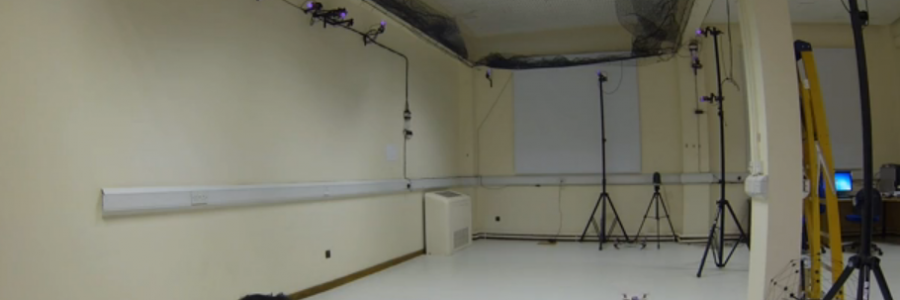
This particular build is a one of our research work-horse/test-bed quadrotor that I build for the MAST Lab. I was in need of a twin brother of my actual quad, to test different FC with different companion computers. I’m actually using a Raspberry pi B+ and Raspberry pi 2, as companion computers, and a PX4 and a MultiWii AIO for flight controllers (I’ll explain later). I have built close to 20 vehicles (perhaps…), and rebuild twice as that… that’s why it took me like a hour and a half from disassembled parts to flying.
What is a quadcopter?
In few words, it’s a vehicle that is lifted and propelled by four rotors. Its also called quadrotor, quadcopter, multicopter, multirotor helicopter, rotorcraft, MRUAV (multi-rotor unmanned aerial vehicle), etc…
The lift in multicopters is generated by two sets of identical fixed pitched vertically oriented propellers; two clockwise (CW) and two counter-clockwise (CCW). These use variation of RPM to control lift and torque. Control of vehicle motion is achieved by altering the rotation rate of one or more rotor discs, thereby changing it’s torque load and thrust/lift characteristics.

Ingredients:
- Tools (tweezers, screwdriver set, small knife)
- Frame
- Motors (4)
- ESC (4)
- Propellers (2 CW and 2 CCW)
- Cables
- Radio with rx/tx module
- LiPo battery
- Flight controller

Then the rest of the recipe is mix all ingredients together and in a hour you will have a quadcopter flying around!! 😀
The frame I choose for this built is a very cheap 330mm glass fiber frame, the size is 330mm which means there is 33 centimeters from rotor to rotor. This frame is about £6. I bought several of this one due to the price, but they break quite easy, you’re now warned!
The motors I had are some SK3 1130kv, this ones have a max power of 125 watts, which is quite nice, pretty powerful small motors! They are brushless.
What is a brushless motor?
Also called BLDC motors or BL motors are synchronous motors that are powered by a DC electric source via an integrated inverter/switching power supply (most commonly know as electronic speed control), which produces an AC electric signal to drive the motor. Brushless DC motors have many advantages over their brushed DC motor counterparts. The most obvious advantage of a brushless motor is its lack of brushes and physical commutator. This difference means that there are many fewer parts that can wear out or break and need to be replaced than in a brushed motor.
Brushless motors, otherwise called outrunners or inrunners, have become very popular with radio controlled airplane hobbyists because of their efficiency, power, longevity and light weight in comparison to traditional brushed motors.
Two key performance parameters of brushless DC motors are the motor constants Kv and Km. Kv being the most popular one. Kv is RPMs per volt, the higher kv motor is faster because at the same voltage it will be spinning a higher rpm. The motors used in this build are 1130 kv, and my battery is 11.1 volts, so:
1130 x 11.1 = 12,543 RPM
This motor will turn at 12,543 revolutions per minute when I give them 11.1 volts… This kv is adequate for this type of build, I will not go into more detail about this (for now…)

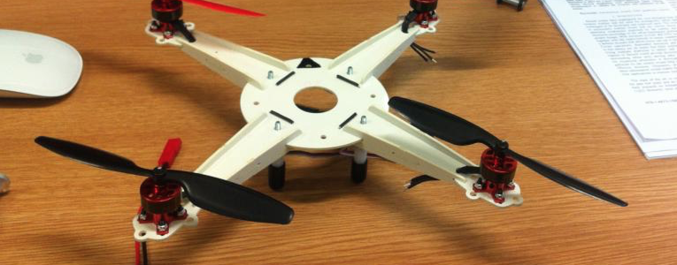
The first step is fixing the motors to the frame arms, as showed in the next pictures:


The next step is to put all the screws in place to finish putting the frame together. You will have something like this:

What is a ESC?
A electronic speed controller is a integrated inverter/switching power supply that will drive BL motors (as stated before…). Brushless ESC systems basically drive tri-phase brushless motors by sending a sequence of signals for rotation. For this built I had laying around 4 Multistar 20amps (maximum) ESC, these are cheap as well, and it will update at 480 Hz.
The default output rate in the RC industry is 50 Hz. The recommended output rate for multicopter ESCs is 400 Hz, in order to minimise latency (NOT because the outputs would require 400 Hz, as multicopter rotors spin only at 80-120 Hz and can’t change speed multiple times during a single revolution). Having 400 Hz or 480 Hz will make the response of the vehicle a lot smoother and nicer.
So, go ahead and place those 4 ESC in your frame, and fix them using cable ties or something similar:

Its important to notice that I’m using a power distribution board, which is just a breakout board with bullet connectors, that will save me the hassle of soldering all cables together, because the power to the ESC must be the same for all of them. You can choose not use it and use a joined cable or something similar.
This is the bottom of the quadcopter with the ESC connected to the distribution board and the motors connected to the ESCs:

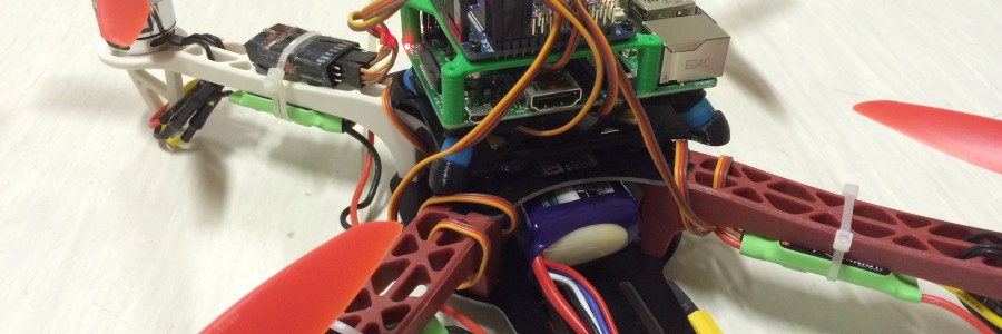
Then the next step is to fix you flight controller… The FC must be close to the center of gravity (CoG), and the must important part is that we need to isolate it from vibrations as much as possible. I usually 3D print a couple of plates and use special cheap rubber balls.
As explained in the beginning of the post, this build is for my research lab, and I’m using the FC with a onboard computer, which makes everything larger…


I’m testing several flight controllers and different architectures, thats the purpose of having two (or more) twin quadcopters, that will behave in a similar way. But thats another story, lets keep on building.
I will join to steps into one, fixing the FC and the props.
What is a fixed pitch propeller?
A propeller is a type of fan that transmits power by converting rotational motion into thrust. A pressure difference is produced between the forward and rear surfaces of the airfoil-shaped blade, and a fluid (such as air or water) is accelerated behind the blade.
“Pitch” describes how much the blade of the propeller is twisted relative to the path it travels as it turns. This is also known as the angle of attack, and is usually measured in inches. Imagine the propeller turning through the water or air. If it moves forward following the angle of the pitch perfectly, and moves forward 10 inches in one full revolution, it is said to have a pitch of 10 inches.
So, if we combine the two definitions, a fixed pitch propeller is a type of prop that cannot be adjusted or changed. It has one pitch, which is usually a compromise between speed and power.
For this quadcopter I’ll be using a 3 blade 7×4.5 (7 inch in diameter with 4.5 in pitch) in plastic, of course in their CW and CCW form, this is also called R (right) and L (left) prop.
Quadcopters can be configured in + (plus) configuration or X (cross) configuration, the props will need to be installed in this manner for each configuration:

Personally, I prefer the X configuration and its the one I use in all of my quads.


What is a flight controller?
This is a topic that could easily extend a lot… But a quick definition would be something like this: Small computer that contains accelerometers, giroscopes, magnetometers and a barometric pressure sensor, that will use this sensors to maintain the vehicle level by sending PWM commands to the ESC.
In a perhaps more practical way, is a computer that will help us to fly a multirotor. The one for this quad is a MultiWii AIO v2 board, that uses a ATMEGA 2560, which is a popular micro-controller because is onboard of Arduinos!
The brain of this flight controller is a high-performance, low-power Atmel 8-bit AVR RISC-based microcontroller combines 256KB ISP flash memory, 8KB SRAM, 4KB EEPROM, 86 general purpose I/O lines, 32 general purpose working registers, real time counter, six flexible timer/counters with compare modes, PWM, 4 USARTs, byte oriented 2-wire serial interface, 16-channel 10-bit A/D converter, and a JTAG interface for on-chip debugging.
And the sensors are this ones:
- MPU6050 6 axis gyro/accelerometer with Motion Processing Unit
- HMC5883L 3-axis digital magnetometer
- MS5611-01BA01 high precision altimeter
Which is also another topic of conversation… but perhaps later.
Its important to notice that without software the above hardware is useless… This FC uses the MultiWii software, which is very popular, easy to change (sometimes) and written in C, well in the Arduino language/IDE.
The configuration of the FC is rather easy, opening the Arduino IDE and the MultiWii.ino file, in the config.h file, we need to setup that this vehicle is a quadcopter in X configuration, the minimum PWM for our ESC, the radio type we have and so forth… This is covered in detail on the MultiWii manual.
After programming and mounting the FC unit, we need to test if the motors are turning in the right direction, we can easily change the direction of the motors, by moving one side of the 3 cables of the ESC/Motor to just another position. More easily explained… if the air is going upwards instead of downwards, them change the position of one of the cables. This needs to be done being very careful. Remember that props rotating a 10000 rpm are super dangerous.


Once this is completed…. oh!!!! I forgot to take pictures when installing the RX… but for that one you just need to plug channel 1 of the RX to the channel 1 port on the FC and so forth.
And now you have a ready to fly quadcopter!!!

And now whats next is to actually perform a test flight, the best idea is just to hover the vehicle at 10-20 cm from the ground and check that everything is okay, then slowly check that the roll and pitch commands are not inverted and that the vehicle is responding nicely and smooth. Remember, flying is everything about small corrections.

Congratulations! you just succeed to create something that flies.
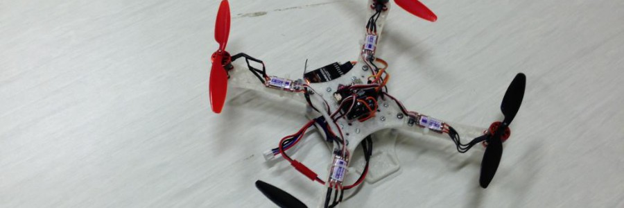
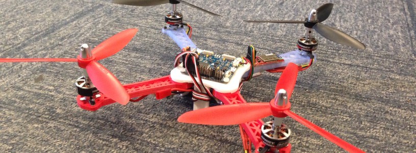
Look at the twins:

And more close ups:


Thanks a lot for reading!


 .
.
 , so, to cheer me up, I start building a tricopter, using a carbon-fiber frame, some powerful motors, a digital servo, some ESC’s and a MW board…


 ) but there is a rotor left who produces torque that tries to spin the tricopter. Because of this, tricopters are usually using a rear servo to tilt the rear rotor to compensate this torque in the same manner a helicopter tail rotor does. The advantage of this solution is more yawing agility in comparison to multicopters with even amounts of rotors.
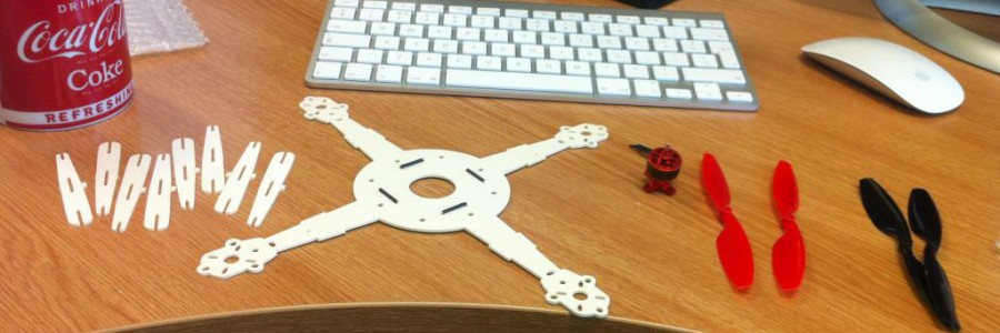


